

Introduction
Pulse jet dust collection systems are widely regarded as the most efficient solution for removing dust from industrial filtration equipment. At the heart of every pulse jet cleaning system is the pulse valve, a fast-acting pneumatic component that delivers precisely timed bursts of compressed air to clean filter bags or cartridges.
Although the pulse valve operates in less than a quarter of a second, its performance has a direct impact on dust collector efficiency, compressed air consumption, filter lifespan, and overall operating costs.
Many engineers understand that pulse valves release compressed air, but fewer understand how the complete cleaning sequence works, how the diaphragm moves, why pressure differences matter, and how the electronic controller coordinates multiple valves.
This guide provides a detailed explanation of the pulse valve working principle, covering every stage of the cleaning cycle and the factors that influence system performance.
What Is the Purpose of a Pulse Valve?
The primary purpose of a pulse valve is to clean filter media without interrupting the filtration process.

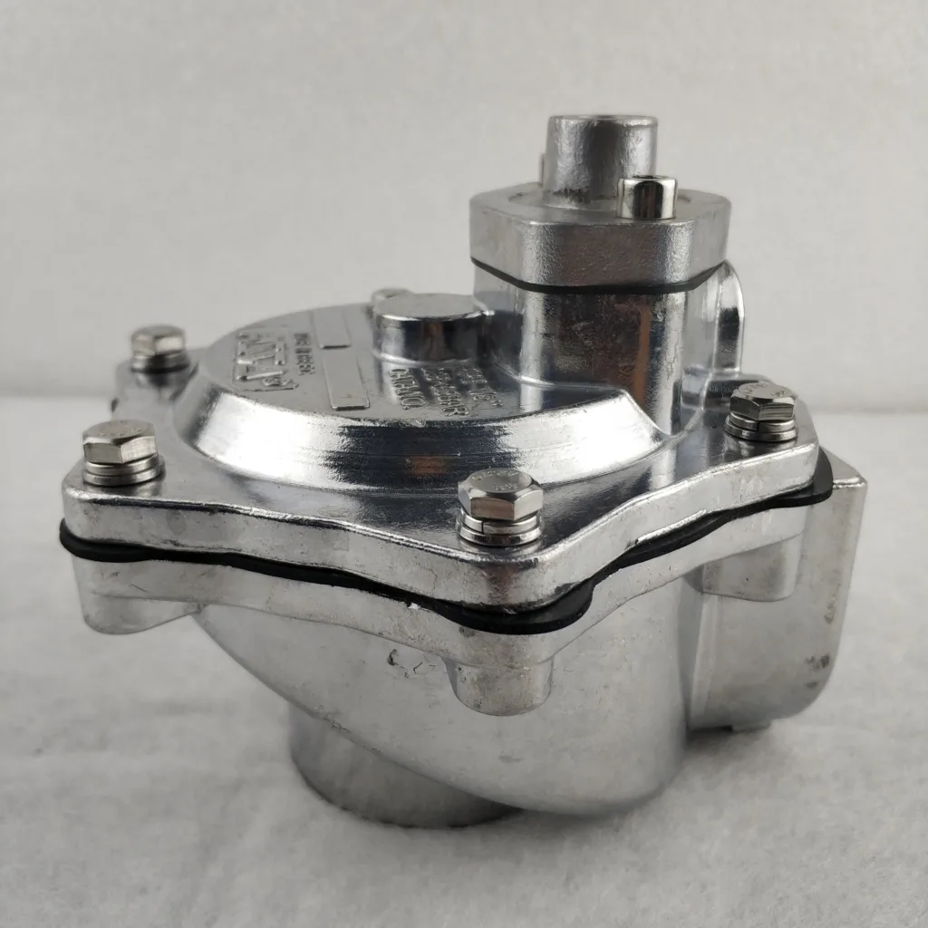
During normal operation, dust particles accumulate on the outer surface of filter bags or filter cartridges. As the dust layer becomes thicker, airflow resistance increases, reducing filtration efficiency and increasing energy consumption.
Rather than stopping production for manual cleaning, pulse jet systems automatically clean the filters by releasing short bursts of compressed air.
Each pulse expands the filter media rapidly, causing the accumulated dust cake to detach and fall into the hopper below. Because only one row of filters is cleaned at a time, the dust collector continues operating throughout the cleaning process.
The Pulse Jet Cleaning Principle
Unlike continuous airflow systems, a pulse valve stores compressed air until a cleaning signal is received. When activated, it releases a large volume of air in a very short period—typically between 50 and 200 milliseconds.
This rapid discharge creates a high-energy pressure wave rather than a steady airflow.
The pressure wave travels through the blow tube and enters the filter bags, where it flexes the filter media outward. The sudden expansion breaks the bond between the dust cake and the filter surface, allowing gravity to carry the loosened dust into the collection hopper.
This cleaning method is highly effective because it combines:
- High-pressure compressed air
- Short pulse duration
- Rapid diaphragm movement
- Sequential electronic control
- Airflow amplification through a Venturi nozzle
Together, these elements produce powerful cleaning while minimizing compressed air consumption.
The Complete Operating Cycle
The pulse valve cleaning sequence consists of several precisely controlled stages.
Stage 1 – Compressed Air Storage
Before the cleaning cycle begins, compressed air is stored in the air manifold connected to the pulse valve.
At this stage:
- The diaphragm is closed.
- Pressure is balanced above and below the diaphragm.
- No compressed air enters the blow tube.
- Dust continues accumulating on the filter bags.
The valve remains in this standby condition until instructed to clean.
Stage 2 – The Pulse Controller Sends a Signal
The electronic pulse controller monitors the dust collector and determines when cleaning is required.
Depending on the system design, cleaning may be triggered by:
- A fixed time interval
- Differential pressure across the filters
- Manual operation
- PLC-based automation
The controller energizes the pilot solenoid valve for a very short period, usually between 50 and 200 milliseconds.
Stage 3 – The Pilot Valve Releases Pressure
When energized, the pilot solenoid valve opens a small exhaust passage.
This allows compressed air above the diaphragm to escape.
As the pressure above the diaphragm decreases, the higher pressure below it forces the diaphragm upward.
This pressure imbalance is what causes the main valve to open.
Because only a small volume of air must be released, the response is extremely fast.
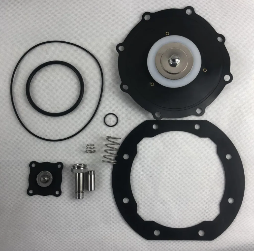
Stage 4 – The Diaphragm Opens
The diaphragm lifts away from the valve seat almost instantly.
Compressed air stored inside the air manifold now rushes into the blow tube.
The valve reaches full opening within milliseconds.
Unlike ordinary pneumatic valves, pulse valves are specifically designed to maximize instantaneous airflow rather than continuous flow.
The rapid opening creates the high-energy pulse needed for efficient filter cleaning.

Stage 5 – Venturi Air Amplification
Most pulse jet dust collectors use a Venturi tube above each filter bag.
As compressed air exits the blow tube nozzle at high speed, it draws surrounding air into the airflow.
This phenomenon increases the total air volume entering the filter bag.
As a result:
- Cleaning becomes more effective.
- Less compressed air is required.
- Energy efficiency improves.
- Dust removal becomes more uniform.
The Venturi effect is one of the reasons pulse jet systems outperform many alternative cleaning methods.
Stage 6 – Dust Cake Removal
The compressed air pulse travels through the filter bag from top to bottom.
The filter expands rapidly before returning to its original shape.
This rapid movement fractures the dust cake attached to the outside surface of the filter media.
The loosened dust falls into the hopper while the fan continues drawing process air through the remaining filter rows.
Because cleaning is completed in a fraction of a second, filtration remains continuous.
Stage 7 – Valve Reset
After the pulse controller removes power from the solenoid, the pilot valve closes.
Compressed air refills the upper chamber.
Pressure equalizes across the diaphragm.
The return spring and air pressure reseat the diaphragm against the valve body.
The pulse valve is immediately ready for the next cleaning cycle.
Why Response Time Matters
A high-quality pulse valve is designed to respond within milliseconds.
Slow valve operation reduces cleaning performance and wastes compressed air.
Rapid response provides several benefits:
- Stronger pressure pulses
- Better dust removal
- Lower compressed air consumption
- Reduced pressure drop
- Longer filter life
- Lower operating costs
For this reason, valve manufacturers focus heavily on diaphragm design, pilot valve efficiency, and airflow optimization.
Factors That Affect Pulse Valve Performance
Several operating conditions influence cleaning effectiveness.
Compressed Air Quality
Clean, dry, oil-free compressed air is essential.
Contaminated air can damage diaphragms, clog pilot passages, and shorten valve life.
Operating Pressure
Most pulse valves operate efficiently between 3 and 8 bar.
Insufficient pressure produces weak cleaning pulses, while excessive pressure accelerates diaphragm wear.
Pulse Duration
Longer pulses consume more compressed air but do not necessarily improve cleaning.
Optimizing pulse duration helps balance cleaning efficiency with energy consumption.
Cleaning Frequency
Cleaning too frequently wastes compressed air and increases diaphragm wear.
Cleaning too infrequently allows excessive dust accumulation and raises differential pressure.
Modern pulse controllers help optimize cleaning intervals based on system conditions.
Common Mistakes That Reduce Cleaning Efficiency
Even with a high-quality pulse valve, several common issues can reduce performance:
- Low compressed air pressure
- Dirty pilot valve
- Damaged diaphragm
- Incorrect controller settings
- Clogged blow tube nozzles
- Air leaks in the manifold
- Moisture in the compressed air system
Routine maintenance and regular inspections help prevent these problems and ensure consistent cleaning performance.